Прежде, чем вы начнете
Технология создания туннелей GRE была добавлена в NSX 6.4. Данная технология реализована c минимальным функционалом, сервисы IPSec и OSPF не видят GRE интерфейсов, так же отсутствет реализация логирования и мониторинга кроме банального пинга. В настоящее время создание GRE туннелей возможно только администраторами NSX через API Rest. Пользователям vCloud данная функция недоступна.
Однако VMWare реализовали создание шифрованных туннелей через функцию Route-Based IPSec VPN. Данная технология идентична Generic Routing Encapsulation (GRE) over IPSec, за исключением того, что перед применением обработки IPSec к пакету не добавляется дополнительная инкапсуляция. В таблице ниже указанно какие вендоры сетевого оборудования поддерживают эту функцию. Отличие от обычного GRE в методах инкапсуляции – в VTI экономится 4 байта путём исключения GRE-заголовка.
| Имя вендора | Поддержка Route-Based IPSec VPN |
|---|---|
| Cisco | да |
| Juniper | да |
| Mikrotik | нет |
Введение
В исходной задаче поставлена цель добиться отказоустойчивости при схеме, когда из удаленного ОФИСА создано два зашифрованных туннеля по одному каналу в строну двух Edge (EDGE-2 и EDGE-3) находящихся в разных датацентрах, но соединенных линией L2. Схему вы можете посмотреть ниже.
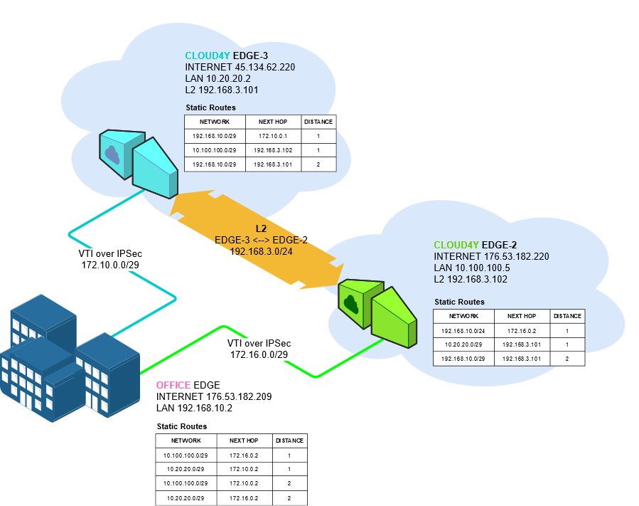
Нам необходимо настроить инфраструктуру таким образом, чтоб при потере соединения между ОФИСОМ и одним из EDGE мы смогли сохранить доступность инфраструктуры находящейся в подсетях 10.20.20.0/29 и 10.100.100.0/29. Для этого необходимо выполнить следующие шаги:
- Развернуть инфраструктуру в каждом VDC (сети, vApp, VM)
- Создать Route-Based IPSec VPN туннели между узлами OFFICE-EDGE-2 и OFFICE-EDGE-3
- На узлах EDGE-2 и EDGE-3 создать статические маршруты поверх GRE к OFFICE.
- На узле OFFICE создать статические маршруты к EDGE-2 и EDGE-3
- Протестировать созданную инфраструктуру на доступность.
- Зафиксировать доступность всех узлов в схеме отключив один из тунелей.
Для эргономики восприятия информации все скриншоты относящиеся к тому или иному узлу будут отмечены цветом согласно маске:
- OFFICE — 45.134.62.220
- EDGE-2 — 176.53.182.220
- EDGE-3 — 176.53.182.209
Узел Office представлен в данной статье на EDGE, но вы можете настроить любое поддерживаемое устройство для построения данной схемы.
Также для уменьшения объема информации, дублирование скриншотов с одинаковых узлов будет сведено к минимуму.
Подготовка инфраструктуры
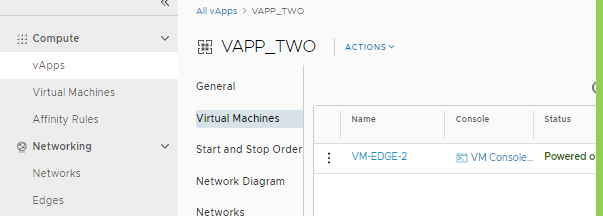
- Cоздаем vApp (VAPP_TWO) и ВМ (VM-EDGE-2) в VDC. То же самое делаем для других узлов.
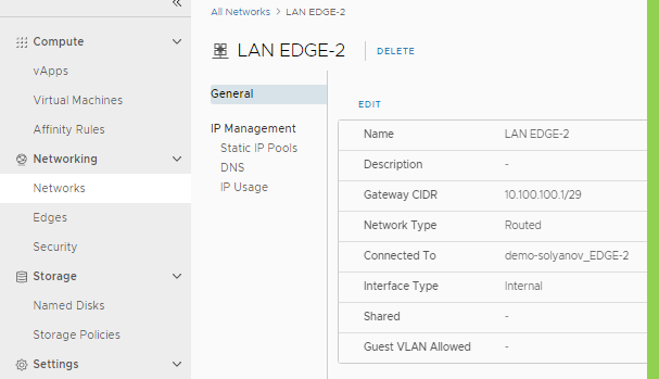
- Создаем сеть LAN EDGE-2 10.100.100.0/29 и подключаем ее к EDGE-2. Тоже самое делаем для EDGE-3 (LAN-EDGE-3 10.20.20.0/29) и для Office (192.168.10.0/29)
- Переходим в настройки EDGE>VPN>IPSec и выбираем создание IPsec VPN Sites
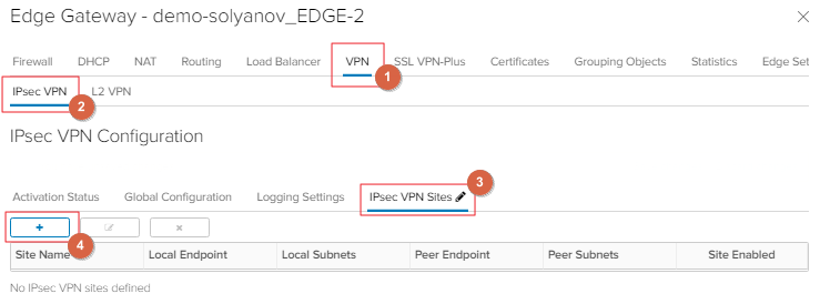
- Создаем Route-Based IPSec согласно матрицы все три узла (со стороны узла Office необходимо настроить два туннеля по одному к каждому узлу EDGE):
Параметр EDGE-3 EDGE-2 OFFICE Name TO Office To Office To EDGE-1, To EDGE-2 Local ID 176.53.182.220 45.134.62.220 176.53.182.209 Peer Subnets 0.0.0.0/0 0.0.0.0/0 0.0.0.0/0 Encryption Algorithm AES-256 AES-256 AES-256 Peer Subnets 0.0.0.0/0 0.0.0.0/0 0.0.0.0/0 Encryption Algorithm AES-256 AES-256 AES-256 Authentication PSK PSK PSK Pre-Shared Key *** *** *** Diffie-Hellman Group DH14 DH14 DH14 Digest Algorithm SHA-256 SHA-256 SHA-256 IKE Option iKEv-2 iKEv-2 iKEv-2 Session Type Route-Based Session Route-Based Session Route-Based Session Tunnel Interface IP CIDR 172.16.0.2/30 172.10.0.2/30 172.16.0.1/30, 172.10.0.1/30 Tunnel Interface MTU 1500 1500 1500 - Настраиваем статические маршруты между созданными туннелями на каждом узле.
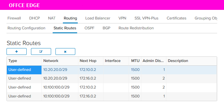
SOURCE NETWORK NEXT HOP DISTANCE EDGE-3 to EDGE-2 (L2) 10.100.100.0/29 192.168.3.102 1 EDGE-3 to Office (VTI) 192.168.10.0/29 172.10.0.1 1 EDGE-3 to Office через EDGE-2 192.168.10.0/29 192.168.3.102 2 EDGE-2 to EDGE-3 (L2) 10.20.20.0/29 192.168.3.101 1 EDGE-2 to Office (VTI) 192.168.10.0/29 172.16.0.1 1 EDGE-2 to Office через EDGE-3 192.168.10.0/29 192.168.3.101 2
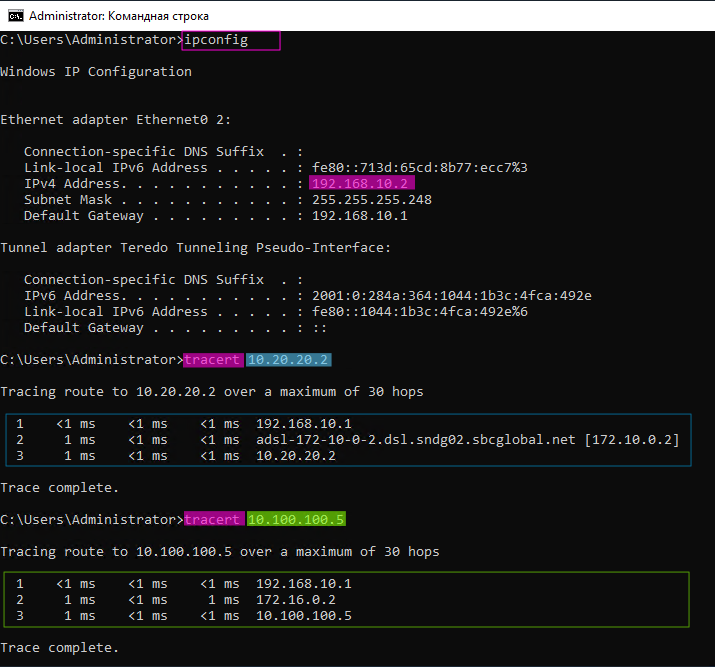
При создании Static Routes в поле Network указываем подсеть находящуюся за противоположным узлом. В поле Next Hop указываем IP адрес туннеля IPSec противоположного узла. - С узла Office фиксируем доступность подсетей подключенных к EDGE-2 и EDGE-3
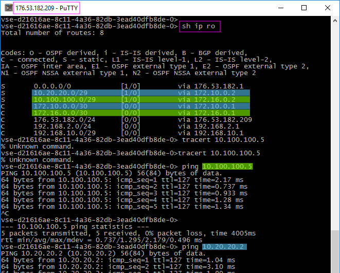
- Фиксируем прохождение трафика к подсетям через созданные туннели
- Cоздаем vApp (VAPP_TWO) и ВМ (VM-EDGE-2) в VDC. То же самое делаем для других узлов.
Проверка доступности после отключения туннеля
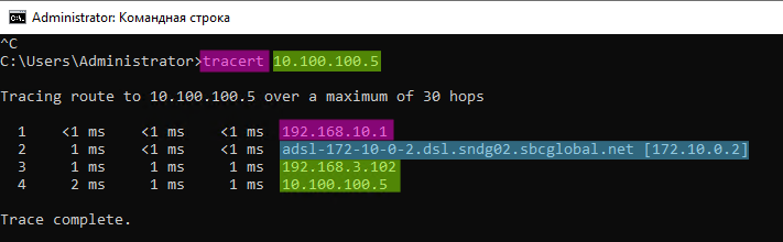
- Когда все узлы имееют логическую связанность, нам необходимо отключить туннель на маршруте Office > EDGE-2 (172.16.0.0/30) чтоб проверить, что маршрут к подсети находящейся за узлом EDGE-2 будет проходить через EDGE-3. Для этого выключаем IPSec VTI туннель на узле EDGE-2.
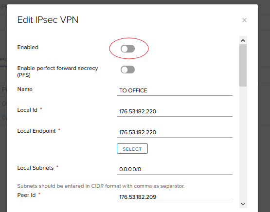
- Теперь фиксируем, что подсеть на узле EDGE-2 остается доступной, но уже по маршруту через узел EDGE-3
- Так же проверяем доступность Office c узла EDGE-2
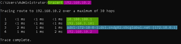
Как видим, доступность узла сохранилась, соответствено отказоустойчивость зафиксирована.
- Когда все узлы имееют логическую связанность, нам необходимо отключить туннель на маршруте Office > EDGE-2 (172.16.0.0/30) чтоб проверить, что маршрут к подсети находящейся за узлом EDGE-2 будет проходить через EDGE-3. Для этого выключаем IPSec VTI туннель на узле EDGE-2.
